|
Personal Emergency Response Systems
Introduction
“Help at your fingertips”, “Help is one call away”, these are the phases used by advertisement for Personal Emergency Response System (PERS), referring the function and ability the PERS. A typical PERS have a pendant (or transmitter), a programmable base unit, which programmed to call the emergency response center. The pendant is designed to wear by the user, and communicate with the base unit wirelessly through radio frequency (RF). The button pushed on the pendant is transmitted to the base unit. And the base unit responses with phone call to the emergency response center.

The challenges
The few of latest the PERS have two ways voice function, which allow emergency response center talk to the user. The challenge is to implement the two ways voice function into the size of the pendant and keep the long lasting battery life. The following is wish list for new generation of PERS:
- Reliable
- Longer range
- 2-way voice and good sound quality
- Small and light weight
- Long battery life
The answer to the challenges
The challenges for the new generation of PERS were responded by the Rich-Tech’s design team. The reliability issues was addressed by the digital technologies, scan for noise free channel first and continuously monitor and switch channels to avoid interference. The “long range” requirement was addressed by the error detection and error correction algorithms, which recover the data and maintain the sound quality in weak signal condition. The sound quality was improved by careful selection of voice codec and fine tuned parameters with experiments. In additional, advance technologies like echo cancellation was used to further enhance the sound quality. Light weight, small size and low power consumption are properties inherited from the digital technologies and TI’s low power RF IC design.
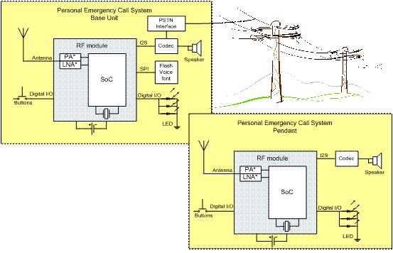
The PERS has three main parts: base unit, pendant, and emergency respond center. RF modules are the key components for both the base unit and the pendant. The block diagram above shows the functional blocks and connections for both the base unit and the pendant.
Reference
http://www.ftc.gov/bcp/edu/pubs/consumer/products/pro24.shtm
http://www.prlog.org/10299978-freedom-alert-no-fee-medical-alert-now-shipping-order-yours-today.html
http://www.telecareaware.com/index.php/freedom-alert-logicmark-mar09.html
http://www.lifelinesys.com/content/how-lifeline-works/index.jsp
 
|